Part 1: Polarization optics
Polarization of light has been and continues to be a subject of intensive research. The modern era of polarization began in the early 19th century. In 1808, Etienne-Louis Malus made a crucial discovery while looking at the setting sun through a crystal of Iceland spar. He observed that the intensity of the reflected light changed when he rotated the crystal. He further studied this phenomenon and showed that this behavior was not only restricted to Iceland spar but could be generally observed in any ordinary substance. His work led to the famous Malus Law which is a relation for the transmitted intensity through a polarizer as a function of incident polarization.
In 1812, Sir David Brewster built upon the work of Malus and showed that for a given material, there exists a unique angle of incidence for which light is fully transmitted or reflected depending on its polarization. This angle is known as Brewster angle. A more general description was given by Augustine-Jean Fresnel who deduced the so-called Fresnel equations which describes the behavior of light at the boundary of two media with different refractive indices, including the effects of polarization.
These groundbreaking discoveries have led to the emergence of new fields of fundamental physics such as quantum optics and have also resulted in several technological applications which have made their way to our daily lives.
In the next sections we will revisit these discoveries experimentally and learn the basics of polarization of light by answering the following questions:
How do we show that light is polarized?
How do we characterize the polarization of light?
How do we manipulate the polarization of light?
Theory
Light can be described as an electromagnetic wave. A wave travelling in the \(z\)-direction looks like:
with the wave vector \(k=2\pi/\lambda\). The electric field-vector \(\vec{E}\), the magnetic field-vector \(\vec{B}\) and the direction of propagation \(\hat{e}_z\) create an orthogonal system. Polarization describes the plane in which the electric field or the polarization vector \(\vec{P}\) is oscillating. One can observe \(\vec{P}\) in the plane perpendicular to the direction of propagation and distinguish between three types of polarization:
Linear polarization: The electric field \(\vec{E}\) is oscillating along a straight line in the plane of polarization.
Elliptic polarization: \(\vec{E}\) describes an ellipse. If the main axes of this ellipse are parallel to the transverse cartesian coordinates, the wave can be written as 1:
Circular polarization: \(\vec{E}\) describes a circle, this is a special case of elliptic polarization.
A linear polarized wave can be thought split up in two other linear waves, that are in phase if their addition gives back the original polarization.
It is also possible to obtain a linear polarized wave by adding two counter-rotating circular polarized waves.
Elliptic polarization can be written as a superposition of two linear polarized waves with a phase shift of \(\pi/2\). The maximum amplitudes of both waves give the main axes of the ellipse in the plane perpendicular to the propagation. For equal amplitudes in both directions one gets circularly polarized light.
In general, natural light, emitted by atoms and thermal light sources, is not polarized. To achieve polarization additional interaction between light and matter or matter-surfaces is needed.
Reflection and Polarization
If dielectric media are interacting with light the molecules are excited to dipole oscillations. When a wave hits a surface between two different media with refractive indices \(n_1\) and \(n_2\) the beam is split in a reflected beam and a refracted one. The refraction angle \(\alpha_2\) is given by Snell’s Law:
The angles are taken between the beam and the normal vector to the surface in the plane of incidence, being the plane parallel to the beams and perpendicular to the surface. The reflection angle is \(\alpha_1\). (Recall that for reflection: \(\alpha_{\mathrm{in}} = \alpha_{\mathrm{out}}\))
To calculate the amplitudes and intensities of the reflected and refracted beams, one has to separately observe the polarizations parallel or perpendicular to the plane of incidence.
Starting from Maxwells Equations and the resulting surface conditions for \(\vec{D}\), \(\vec{E}\), \(\vec{H}\) and \(\vec{B}\) one can calculate the amplitude coefficients for the reflection \(r\) and for the transmitted beam \(t\). These are the square roots of the intensity coefficients \(R\) and \(T\). For the calculations the reader is referred to the literature.
For a polarization perpendicular to the plane of incidence (also called TE-mode for Transversal-Electric, in German: S-Polarization) the results are:
For the wave polarized parallel to the plane of incidence (TM, Transversal-Magnetic mode, in German: P-Polarization) the reflection and transmission coefficients \(r\) and \(t\) are: $\( r_{TM}=\frac{\tan\left(\alpha_1 - \alpha_2\right)}{\tan\left(\alpha_1 + \alpha_2\right)} \)$
The minus sign in equation (1) shows that for a perpendicular polarization a phase shift of \(\pi\) appears at the surface.
Birefringence (Doppelbrechung)
Linear, isotropic, homogeneous media have the property that for each spatial direction in which light is propagating through it, the index of refraction \(n\), and thus the velocity of light, is the same. In these media, such as crystals with cubic symmetry, one finds the simple proportionality \(\vec{D}=\varepsilon \vec{E},\) where the permittivity \(\varepsilon=n^2\) is a scalar. For anisotropic media \(\varepsilon\) becomes a symmetric tensor \(\varepsilon_{ij}\). This means that the refractive index is now different for the main axes of the crystal and for different planes of polarization of the light propagating along them.
One has to differentiate between uniaxial and biaxial media. Uniaxial media have one axis that is called optical axis. When light is travelling through the crystal along the optical axis, the index of refraction it encounters is equal for both polarization directions. On the axes perpendicular to the optical axis one finds so-called ordinary and extraordinary indices of refraction.
If one expands \(n\) to three dimensions, meaning for each possible direction of propagation for light in the crystal, one obtains an ellipsoid whose main axes coincide with the axes along which light experiences only a single \(n\). This ellipsoid, shown in Fig. 1, is called the indicatrix. (Which axis is the ordinary axis or extraordinary axis depends on the symmetry of the crystal, additional details can be found in the literature.)
To find out what index of refraction a wave experiences, one has to decompose the light in linear polarized waves along two axes \(a\) and \(b\), and then calculate the indices \(n_a\) and \(n_b\). Here, this is shown in general. In all practical cases, one would try and decompose the wave along the main axis to simplify the problem, because if light is polarized along an optical axis it ‘sees’ only one index of refraction.
Biaxial crystals show a more complicated indicatrix. In those cases it is usually not an ellipsoid, and the main axes do not coincide with the optical axes.
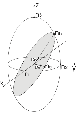
Fig. 1 Indicatrix or index-ellipsoid for an uniaxial medium.
Wave plates (retarders)
Wave plates are birefringent crystals with a thickness of \(\left(m+\tfrac{1}{4}\right) \lambda\) with \(m\) an integer (quarter wave plate) or \(\left(m+\tfrac{1}{2}\right) \lambda\) (half- wave plate). They are used to change a certain polarization state of incident light into another state. In this case the expressions ordinary axis and extraordinary axis are not used, instead the axes get their name simply by the value of the refractive index along the axis: fast and slow axis.
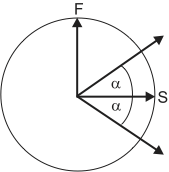
Fig. 2 Rotation of polarization in a half-wave plate.
Waves travelling along the different optical axes of a half-wave plate experience a phase shift of \(\pi\) relative to each other, so that their relative optical retardation is half a wavelength. For linear polarized light this means that the wave will leave the retarded again linear polarized, but the plane of polarization will be rotated by twice the angle it had to the optical axes when it entered the wave plate, as shown in figure Fig. 2. For the special case of \(\alpha=45^\circ\) the polarization will be rotated by \(90^\circ\).
Quarter-wave plates give a relative phase shift of \(\pi/2\) to waves propagating along the axes. This means that they turn linear polarized light into elliptically polarized light or the other way around. For linear polarized light incident at \(\alpha=45^\circ\) one obtains circularly polarized light.
Experiments: polarizers and wave plates
In this first part, you should get used to the optical devices you will use throughout the experiments of this lab-course: polarizers, polarizing and non-polarizing beam splitters and wave plates (retarders). If your initial state of the light is polarized, you can cross-check your results afterwards by applying the matrix Jones formalism.
Take a glass plate. Use it to partially reflect the incident laser light and find the Brewster’s angle. Explain your observations. What happens when you use other optical devices after it? Use the reflected light at the Brewster’s angle to understand the effect of other optical elements such as polarizers and beam splitters.
Fix the position of the first glass plate at the Brewster’s angle. Take a second glass plate and use it to reflect the light coming from the first glass plate. Build it up such that the plane of incidence is perpendicular to the previous one. What happens to the light after the second reflection? Explain your understanding of what happens to the light in the first glass plate at the Brewster’s angle, according to your observations in the second one.
Take two polarizers and calibrate them. In order to calibrate them, you have to find the polarization axis. Use the reflected light at the first Brewster’s glass plate for such purpose (make sure that you are still working at the Brewster’s angle!). How can you set a reference to calibrate the polarization axis of polarizers and polarizing beam splitters (PBS)? Find a way based on the reflection properties of the light at a surface.
Check if your laser is polarized.
Find out how the light which is reflected by or passing through the beam splitters is polarized. How do they work? Calibrate the type of beam splitters and the type of polarization that they might induce.
Build a setup to test the waveplates: Find a position at which the half-waveplates rotate the incident polarization by \(90^\circ\).
Find a position at which the quarter-waveplates produce circular polarized light.
Perform the experiments sketched in Fig. Fig. 3 and Fig. 4: set up two quarter wave plates behind each other and find out what they do with the polarization of light passing through both plates. Then take the second quarter wave plate and turn it around on its post by \(180^\circ\), so that the beam traverses the wave plate in the opposite direction. Do this for both combinations of input polarization vs.\ wave plate orientation shown in the figures. What do you expect? What do you observe? Find an explanation for the effects; what is the difference between both experiments?
Use a mirror to reflect linearly polarized light in a straight angle (\(>90^\circ\)) and measure the polarization of the reflected light. Repeat for a linear polarization perpendicular to that of the previous experiment. Where does the phase shift of \(180^\circ\) occur?
Send linear polarized light through two quarter wave plates with their axes at \(45^\circ\) with respect to the plane of polarization and check the output polarization (either case of Fig. 3 or Fig. 4). Now change the setup to contain a mirror between the two waveplates which reflects the light at a straight angle ( \(>90^\circ\)). Check the output polarization again. Explain your observations.

Fig. 3 Operations of quarter wave plates with different orientations
Think about what happens to a polarized light beam which passes through a quarter wave plate and is then reflected by a mirror perpendicular to its path so that it passes again through the same wave plate on the way back. How does the outcome depend on the orientation of the wave plate relative to the incident polarization? Design and perform an experiment to prove your theory.
Repeat the previous experiment for a half-wave plate.
Look into the light of a white lamp through the optical isolator. Do so in both directions of the isolator and explain your observations. How would you have to insert the isolator into the laser beam to see the isolation effect? Test your hypothesis.
Compare your results on the polarization of the laser beam with the output of the polarization analyzer.
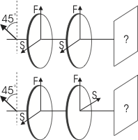
Fig. 4 Operations of quarter wave plates with different orientations; here you might have to first rotate the incoming polarization.
- 1
\(+\) gives clockwise polarization, \(-\) counterclockwise. The names are given by observing the wave propagating to the observer, but you might also find the opposite definition in modern books