Part 2: Electro-optic effect
Theory
Some materials change their optical properties when they are brought into an electric field. To use this effect one needs an electro-optic medium, such as some cubic crystals; they called electro-optical modulators (EOM). In that case, the refractive index \(n\) of the medium becomes a function of the applied field \(n=n(E)\). Since the variations of \(n\) with \(E\) are only small, \(n(E)\) can be expanded in a Taylor series about \(E=0\):
Using the coefficients
and neglecting higher order terms, one can rewrite \(n(E)\) as
Typical values for \(r\) are \(10^{-12}\) to \(10^{-10}\) m/V. It is sometimes convenient to use the electric permittivity instead of the refractive index: \( \eta=\varepsilon_{0}/\varepsilon \). With
this yields
For \(r \gg s\) we obtain the linear electro-optic effect or Pockels Effect, where the refractive index depends linearly on the applied field. In that case the equations are reduced to \(\eta=\eta_{0}+rE\) and
Where \(r\) is called the Pockels coefficient.
Similarly, when \(r \ll s\), we can see from Eq. (3) that we obtain a quadratic dependence of refractive index on the electric field. This is known as the Kerr effect, which will not be studied here.
Since the electro-optic crystals are generally birefringent, the effect of the index of refraction on the light is governed by the relative orientation of the electric field, the crystal axes and the beam path. Thus, the Pockels coefficient \(r\) in Eq. (2) is actually only one entry from a Pockels coefficient-tensor.
Since the index ellipsoid, the indicatrix, can now no longer be written with just the principal axes, we have to revert to its general form:
We thus obtain for the different components:
The entries in the \(r\) matrix are constrained by the crystal symmetry. The typical magnitudes for the \(r_{ij}\)-coefficients are \(10^{-12}\) m/V. The material used in the practicum is LiNbO\(_{3}\). It is a uniaxial crystal with a crystal symmetry \(3m\) and it has indices of refraction \(n_{1}=n_{2}=n_{o} , n_{3}=n_{e}\). The Pockels Coefficients for LiNbO\(_3\) are:
Where the first matrix shows the general case for crystals with \(3m\) symmetry. However, the Pockels coefficients are very hard to measure reliably and they can be affected strongly by contaminants inside the crystal. Therefore, the above numerical values are only indicative 1.
For the case of a crystal without an applied field, the indicatrix is given by
Depending on the direction of the applied electric field and the direction of the light through the crystal, several distinct situations are possible. Each assembly shows a different behaviour.
One of the most widespread orientations is with the Pockels cell having a longitudinal field, i.e. applied along the extraordinary axis, \(z\), and the light also travelling along that axis. This means that the light passes through transparent electrodes. In a cell with a transverse field the electric field can be applied along the ordinary axis, \(x\), and the light then travels along the extraordinary axis, the optical axis \(z\).
The Pockels cell of this practicum, however, has the electric field applied along the extraordinary axis \(z\), with the light travelling along one of the ordinary axes, the \(y\)-axis. In this case, the applied electric field \(\vec{E} = E_z\) modifies the indicatrix to:
This equation can be cast in the form of Eq. (5)
with the modified ordinary and extraordinary indices of refraction \(n_{o}'(E)\) and \(n_{e}'(E)\) given by
With the approximation \( 1/\sqrt{1+x} \approx 1-\tfrac{1}{2} x \) for small \(x\), we can indeed rewrite these indices of refraction in the manner we have seen before in Eqs. (2) and (4):
The Pockels Cell
An electro-optic crystal between two capacitor plates is called an electro-optical modulator. When the crystal exhibits the Pockels effect it is called a Pockels cell.
For light with a wavelength \(\lambda\) travelling through a medium of length \(L\) with an index of refraction \(n\), the incurred phase in the medium is given by:
Since each ordinary and extraordinary axis, has a different index of refraction, \(n_o\) and \(n_e\), respectively. Light travelling through a birefringent crystal experiences a phase retardation \(\Delta\Phi\) between the two polarizations equal to
With a Pockels cell one can manipulate both \(n_o\) and \(n_e\) by the strength of the electric field, as outlined above. The phase retardation \(\Delta\Phi\) due to a Pockels cell with an applied field \(E\) is thus given by $\( \Delta \Phi(E)=\frac{2\pi}{\lambda} \left(n_e'(E)-n_o'(E)\right)L. \)$
using the approximations of Eqs. (6) this becomes:
With the applied voltage \(V=Ed\) we thus obtain that the retardation is given by Eq. (8):
where
are the retardation for \(V=0\) and the so called half-wave voltage, respectively. At \(V=V_\pi\) the relative phase retardation between the two polarizations is \(\pi\), causing the Pockels cell to act as a half-wave plate.
Transverse Intensity Modulation
One can use a Pockels Cell to modulate the intensity of light. As we have seen, the relative phase retardation between the two polarizations is variable. For intensity modulation, one needs to put the Pockels cell between two crossed polarizers, placed at \(45^\circ\) with respect to the optical axes of the crystal. This set-up has an intensity transmittance \(T = \sin^2 (\Phi/2)\). With equation (7) the transmittance of the device then is a periodic function of V:
The device can also be used as a linear modulator if the system is operated in the region near \( T(V)=1/2\).
Optical Activity and Faraday-Effect
Optically active media rotate the plane of polarization of linear polarized light. As described above, one can treat linear polarization as a superposition of two circular polarized waves with the opposite direction of rotation. In an optically active medium these two circular waves have different phase velocities, and thus the resulting linear polarized wave turns its plane of polarization. Natural optical activity appears in chiral media, such as solutions of dextrose or lactic acid. For these media, the direction of rotation does not depend on the direction of propagation through them; the behaviour is symmetric.
Some media become optically active when an axial magnetic field is applied, which is known as the Faraday effect. In this case the direction of rotation does depend on the direction of propagation, because the B-Field determines a spatial axis and thus breaks symmetry. The angle by which the polarization is rotated depends on the length of the medium \(L\), on the magnetic field strength \(|\vec{B}|\) and on the so-called Verdet constant \(\upsilon\):
The Verdet constant is a function of the wavelength: $\( \upsilon=-\frac{\pi\gamma}{\lambda n} \)$
where the magnetogyration coefficient \(\gamma\) is a material constant of the medium.
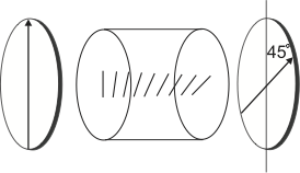
Fig. 5 A Faraday isolator or optical diode
The Faraday effect can be used to build an optical isolator. An optical isolator consists of a medium sensitive to the Faraday effect in an axial magnetic field. The set-up is enclosed by two polarizers with an angle of \(45^\circ\) to each other, as shown in figure Fig. 5. In an optical isolator the first polarizer defines a plane of linear polarization of the light incident on the optically active medium inside the isolator. The medium rotates the plane of polarization by \(45^\circ\) clockwise, so that the light can pass the rear polarizer.
Light entering the isolator from the other side will first be polarization filtered by the rear polarizer. The plane of polarization is then rotated again by \(45^\circ\) by the medium, this time counter-clockwise. The result is that the polarization is finally rotated perpendicular to the front polarizer, thus it is absorbed. In this way the optical isolator is a one-way device for light, so that is also known as an optical diode. Note that the length of the active medium and the magnetic field determine the amount by which the polarization is rotated, so that optical isolators need to be designed to the wavelength of the used light in order to work properly.
Experiment
In this part you will get a feeling of how an electric field (a voltage) can alter the optical properties of a crystal, in the sense that the refractive index of the material is changed. In the first few experiments you will measure the change of the index of refraction directly. In the second set of experiments, you will study the extent of the manipulation by its effect on the polarization state of light transmitted through the crystal.
The electric field is usually applied in the direction of the optical axis of the crystal. There are two possibilities for the direction of the light: parallel or perpendicular to the electric field. In the set-up used in this lab-course, the electric field is along the optical axis and the laser beam is incident perpendicular to the field. Take a closer look at the device; you can clearly see the (copper) electrodes against the crystal. (Don’t do this when the laser is on…)
Since the electro-optic effects are only rather small, one needs a high voltage to drive the Pockels cell. The high voltage power supply used to drive the Pockels cell can be controlled by the dials on its front, see Fig. 6.
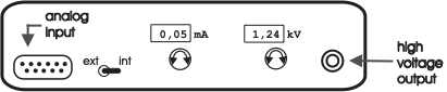
Fig. 6 Front view of the high voltage power supply used to drive the Pockels cell.
The preferred way during the practicum, however, is to control the high voltage supply using a control voltage, applied to the analog input on the front panel of the power supply. A periodic input signal will cause an accordingly varying output voltage, e.g. you can sweep the voltage on the Pockels cell using a sawtooth wave form. The toggle-switch determines whether the power supply is controlled by the dial-settings (Int) or by the input voltage (Ext). Note, however, that the output voltage or current can never exceed the internal control settings (as set with the dials), even when using the analog input: make sure that you set the output range correctly. The output voltage and current are indicated on the displays of the power supply.
An input voltage between 0V and \(\sim 10\)V at the analog input results in an output voltage between 0V and \(\sim3\)kV. The voltage applied to the Pockels cell should not exceed 2kV. A voltage range between 0V and 1.8kV produces sufficient data to evaluate.
Characterization of the high voltage supply / Familiarization with the set-up
During the experiments you will need to measure the desired optical signal with a photodiode against the voltage on the Pockels cell. The oscilloscope cannot handle the high voltage, but you can measure the control voltage on the analog input of the high voltage supply. Therefore, you need to know the voltage amplification factor of the high voltage power supply. The power supply is built for low frequency modulation, so either use a low frequency modulation or the output of the low voltage power supply.
First step: Measure the amplification factor of the high voltage amplifier / power supply.
Switch off the high voltage power supply. Leave the power supply connected to the filter-box, but disconnect the Pockels cell from the filter-box in order no to harm the cell inadvertently. The filter-box remains connected to discharge the high-voltage output and to let you check whether the current-settings of the high voltage power supply are not too low. To disconnect the cell from the filter-box: disconnect the cables on the filter-box side so that you can measure the entire set-up without high voltage risks, such as short-circuiting etc. due to having open cables next to a steel table.
Next, connect the dc power supply to the analog input of the high voltage power supply. Set the toggle switch to Ext.
Since the oscilloscope cannot take more than 300V, you cannot measure the high voltage signal directly; you will have to rely on the indicators on the display of the power supply.
Evaluate your measurements in your log book (Is the amplification linear? Can you use your data points or do they scatter too much? What limits should you set on the input voltage the not to harm the Pockels cell? etc.) before proceeding with the next step.
Second step: Set up the function generator and the oscilloscope for the following series of experiments
Connect the function-generator to the oscilloscope and display a full period on the screen with a frequency of \(\sim0.6 - 1\)Hz.
Adjust the amplitude and offset of the function generator correctly, so that the Pockels cell will survive (\(V_{\mathrm{output}}=0-1800\)V).
Hint: make your adjustments of the function generator at a high frequency (\(\sim\)kHz) to have an accurate feedback on your changes. Don’t forget to switch back to low frequencies when actually measuring.
Parameter |
value |
|---|---|
Optical wavelength |
\(\lambda=632.8\)~nm |
Pockels cell material |
LiNbO\(_3\) |
Electrode separation |
\(d=2\)~mm |
Crystal length |
\(L=20\)~mm |
Indices of refraction |
\(n_o=2.286\) |
at \(\lambda=633\)~nm |
\(n_e=2.200\) |
Mach-Zehnder interferometer
To determine whether light undergoes a phase shift and to which extent, one needs a set-up that compares the phase of the original laser beam with the phase of the light transmitted through the Pockels cell. Here, a Mach-Zehnder interferometer is useful. A Mach-Zehnder interferometer consists of two non-polarizing (Why?) beam splitters and two (totally reflecting) mirrors, see Fig. 7. Since the two beams travel independently and spatially separated through the interferometer, phase shifts can be introduced to a single beam, without affecting the other one. The result of the phase shift can be determined by the intensity output. Due to the two separated beams, a Mach-Zehnder Interferometer is difficult to align, but its high sensitivity to phase shifts makes it useful for various applications.

Fig. 7 Set-up for phase modulation within a Mach-Zehnder Interferometer
The intensity at one output port of the interferometer is \(I_{\mathrm{out}}\) is related to the incident intensity \(I_{\mathrm {in}}\) by
where \(\phi=\phi_1-\phi_2\) is the phase difference between the light beams passing through the branches 1 and 2. For the transmittance we have:
If the Pockels cell is placed in branch 1, we get
Yielding the following relation between \(\phi\) and the applied voltage:
where the constant \(\phi_0=\left(\phi_1-\phi_2\right)_0\) includes the path difference between the two branches. (In this set-up \(\phi_0 = 0\), but in other books you might find other types of Mach Zehnder Interferometers.)
We finally obtain for the transmittance:
ToDo
First step: Determine the directions of the optical axes of the Pockels cell (see also chapter on Part 1 and the table above). Construct a Mach-Zehnder Interferometer with the electro-optical modulator in one arm.
Set up the first beam splitter and the mirrors. It is recommended to have the beams all lying in the same, horizontal, plane. If this is impossible, the original laser beam might not be parallel to the optical table, or the first beam splitter is tilted. The former can be corrected by using a so-called ‘’dog leg’’ before entering the interferometer: use two mirrors to create a Z-shaped laser beam path, which allows you to align the laser beam in every possible direction. The latter problem can be corrected with the screws of the mounting of the beam splitting cube.
Next, adjust the mirrors so that both laser beams cross (again, preferably in the same horizontal plane) at a certain point, preferably with the beam paths perpendicular to each other.
Insert the second beam splitter. The point where the two beams cross has to be at the beam splitting interface within the cube. You will have a good approximation of this when the beams enter the cube at the same position (in the center of the surface, ideally) and/or if they seem to overlap directly after the cube in both exit ports of the interferometer.
Now, adjust the second beam splitter so that both beams in at least one exit port overlap. At a proper alignment you will be rewarded with an interference pattern in the exit beams. It is helpful to use a lens to widen up the beam, so that you can detect the interference pattern more easily.
To measure the phase difference, adjust the interferometer so that you see \(\sim 3 - 5\) interference maxima in the laser beam. Widen up the interference pattern with a lens so that the fringe spacing is approx. 2mm at the position of the photodiode and project only the maximum of a single fringe (Why?) onto the photodiode (use an iris).
In general: Keep in mind that you can only influence reflected beams, not those transmitted by beam splitters. Also note that a large interferometer is more sensitive to noise (vibrations from walking around etc.).
Now set up the measurement
Make sure you have determined the correct position/orientation of the Pockels cell with respect to the polarization of the incident light.
Make sure that you do not saturate the photodiode (\(V_{\mathrm{out}}<3\)V).
Measure the output intensity as a function of the applied voltage for both crystal axes.
Compare the result for both \(\pm90^\circ\) axes. What effect does a rotation of \(180^\circ\) of the Pockels cell have?
Evaluation
Determine the half-wave voltage \(U_\pi\) for both crystal axes.
Determine the Pockels coefficients \(r_{13}\) and \(r_{33}\).
Just for fun: connect the loudspeaker to the photodiode and tap lightly on the table next to the interferometer; can you explain what you hear and what you see in the interference pattern?
Polarization Manipulation / Intensity Modulation
The Pockels cell is a birefringent crystal, with both the fast axis and the slow axis voltage dependent, the device acts as an arbitrary-wave retarder. To understand this fact we have to observe the phase difference between both perpendicular planes of linear polarization. As explained in the theory section, this phase difference is given by
where
and
are the retardation for \(V=0\) and the so called half-wave voltage, respectively. At \(V=V_\pi\) the relative phase retardation between the two polarizations is \(\pi\), causing the Pockels cell to act as a half-wave plate.
The effect of the Pockels cell on the polarization state of transmitted light can be studied in a manner equivalent to the experiments of Part 1. You can measure the intensity of light transmitted by a pair of crossed polarizers with the Pockels cell in between. Here, you will measure the intensity behind the analyzing polarizer with a photodiode as a function of the high voltage applied to the Pockels cell.
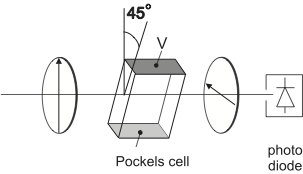
Fig. 8 Experimental Set-up for Transverse Amplitude Modulation
To do
Construct the set-up outlined in Fig. 8, with the Pockels cell placed between two crossed polarizers with their transmission axes at an angle of \(45^\circ\) to the optical axis of the crystal. Why does the Pockels cell need to be at \(45^\circ\)? Make sure you have determined the correct orientation of the Pockels cell. Make sure you will not saturate the photodiode.
Measure the transmitted power on the photodiode as a function of the applied high voltage on the Pockels cell for both orientations \(\pm 45^\circ\). Record your data on the computer.
Evaluation
Use the plots of transmitted power vs. applied voltage for both orientations \(\pm 45^\circ\) to determine the half-wave voltage \(V_\pi\).
What is the difference between the \(\pm 45^\circ\) cases?
If the first intensity maximum is not at 0V: why is that?
Calculate \(V_\pi^{\mathrm{calc}}\) for the Pockels cell, using Eq.(9) and your previously measured values of \(r_{13}\) and \(r_{33}\).
Calculate \({V_\pi^{\mathrm{calc}}}'\) directly from your measured \(\left( U_\pi \right)_e\) and \(\left( U_\pi \right)_o\).
Compare your calculated and measured results to the specifications: \(V_\pi \approx 380\)V.
Linear Amplitude Modulation
Consider the set-up of your previous experiment, see Fig. 8. For a certain range of voltages, the intensity output of the setup shows an almost linear dependency with the applied voltage. This means that it is possible to linearly modulate the intensity of the transmitted light and thus transmit an arbitrary signal optically. For this, one has to modulate the applied voltage to the Pockels cell with the desired signal. For maximum signal amplitude modulation, you have to set up the Pockels cell at this particular voltage, then also a low-voltage signal can suffice to give an appreciable intensity variation. What is the necessary high voltage offset? At this voltage, the Pockels cell acts equivalently to another optical element. Which element is that?

Fig. 9 Voltage range for Linear Amplitude Modulation
To test the possibility of linear amplitude modulation, and to get an idea of the possible response-time of the Pockels cell, use the set-up of the previous experiment, see Fig. 8. Use the ‘internal’ setting of the high voltage supply to apply a DC offset voltage to the Pockels cell. Use the function generator for a high frequency (\(\sim\)kHz) signal. Add both signals via the filter-box in the set-up; now the Pockels cell will ‘see’ both voltage signals. Compare the function generator / input signal with the photodiode signal on the oscilloscope; optimize the amplitude response of the photodiode (in other words: optimize the modulation efficiency of your set-up) by varying the offset voltage for the Pockels cell.
Evaluation
What happens with the transmitted signal at different offset voltages? Why is that?
At which points can you improve the signal-to-noise ratio? e.g. should you amplify the laser power, the high voltage, the modulation amplitude and/or other parts of the set-up?
Now replace the signal of the function generator with a radio signal and connect the output to a loudspeaker instead of to the oscilloscope. First check with the loudspeaker whether the radio (web-radio from the lab-computer) is turned on and tuned to a radio station. Connect the photodiode to the loudspeaker and listen to the effect of changing the offset voltage on the Pockels cell and varying the orientation of the last polarizer.
Describe and explain your observations.
Note
The fast response of electro-optic modulators to electric field changes is used in LCD-displays and similar devices. Electric fields then switch the orientation of long polymer chains between crossed polarizers to vary the light transmission through the pixel.
- 1
Another source gives for LiNbO\(_3\): \(r_{13}=9.6\), \(r_{22} = 6.8\), \(r_{33} = 30.9\), \(r_{51} = 32.6\). All values in [pm/V].