Part 3: Acousto-Optic Effect
Theory
The refractive index of a crystal can be changed by a sound wave. Since a sound wave is a periodic density modulation, the refractive index itself will also varies periodically. The spatial period of the modulation is the sound wavelength, \(\lambda_s\). A sound wave in a crystal with initial refractive index \(n_0\) can be described by:
\(\Delta n_0\) is the amplitude which is given by the photo-elastic constant \(p\) and the amplitude of the strain (relative displacement) \(s_0\):
This is also proportional to the acoustic intensity.
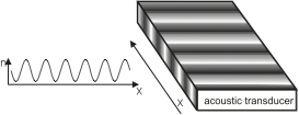
Fig. 10 Modulation of the refractive index by a sound wave
The simplest form of interaction between a laser beam and a sound wave is the so called Bragg diffraction, which appears for long interaction lengths, i.e. wide crystals. Here, the laser beam is reflected partially or totally off planes of equal density in the crystal.

Fig. 11 Deformation of a plane wavefront by a sound wave travelling through a thin crystal
For a short interaction length, i.e. a thin crystal or better a thin sound beam, the Debye-Sears effect appears. Here the sound beam acts as a phase grating: since the laser beam has a certain width, the initial plane wavefront is deformed by travelling through the sound beam. The parts of the light beam travelling through denser areas of the crystal experience a higher index of refraction, than other parts. This means that the parts of the former plane wavefront incur a phase shift relative to each other. In this sense the system is analogous to a grating: in the near field the final wavefront leaving the crystal is bent, in the far field it gives rise to an interference pattern with several higher orders, as shown in Fig. 11.
Since the light interacts with a moving sound wave, the diffracted light is Doppler-shifted. This means that the light in higher orders has a higher or lower frequency, depending on the number of the diffraction order.
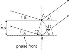
Fig. 12 One can observe a maximum in the far field if light reflected from A and B interferes constructively.
To calculate the diffraction angles, have a look at Fig. 12. Light reflected from A and B interferes constructively, if (12)
where \(\theta_1\) is the incident angle of the light, \(\theta_2\) is the diffraction angle and \(\lambda\) and \(\lambda_s\) are the wavelengths of the light and the sound wave respectively. The Bragg condition for constructive interference is fulfilled when
with \(\theta_B\) the Bragg-angle. In the case of a thin grating, as we have here, we have \(\theta_1 + \theta_2 = 2 \theta_B\), and for a thick grating the more rigorous \(\theta_1=\theta_2=\theta_B\) holds.
Since the sound wave, i.e. the grating, is moving, one should consider the effects of the Doppler shift of a wave reflected on a moving mirror, which is given by
with \(v\) the velocity of the mirror. For the case of the grating in an AOM we have \(v=v_s \sin{\theta_1}\) (see Fig. 12) so that the resonating frequency inside the crystal (the frequency showing constructive interference on the grating) is the one Doppler shifted to:
where \(v_s\) is the sound velocity in the crystal. Using again the Bragg condition \(2 \lambda_s \sin \theta_1 = \lambda\) one sees that
Thus each diffraction spot has a different optical frequency, given by:
or equivalently:
Photon-phonon model
Another way to visualize the effect of an AOM on a light beam is to regard the system as two scattering quasi-particles: a photon and a phonon. Both quasi-particles carry a momentum of \(\hbar \vec{k}_l\) and \(\hbar \vec{k}_s\), respectively, with \(\vec{k}_i\) the wave vector of the interacting waves. Momentum conservation dictates that
and energy conservation dictates
with \(m\) the diffraction order, i.e. the number of phonons the light wave interacted with. Eqs. (10) and (11) show that the outgoing light wave has undergone a change in both frequency and direction with respect to the incident light, proportional to the diffraction order and the used sound frequency. Light beams diffracted by the density variations caused by the sound wave interfere constructively when
where \(\theta_1\) is the angle under which the light enters the crystal and \(\theta_2\) is the diffraction angle.
The dependency of the diffraction efficiency of the AOM, meaning the power transmitted to the first order maximum, relative to the power in the un-diffracted beam, is given by:
where \(L\) is the interaction length of the light beam with the sound wave, \(\lambda\) is the optical wavelength, \(\theta_B\) is the Bragg angle, \(I_s\) is the intensity of the sound wave. \(M_2\) is a figure of merit for the used acousto-optic material 1, in the case of the used TeO\(_2\) the constant is \(M_2 = 34.5\times10^{-15}\)s\(^3\)kg\(^{-1}\). For low sound-input power, the behaviour is approximately linear. For higher sound-input powers the power behaves as a squared sine function, as shown in Fig. 13.
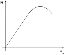
Fig. 13 Relative power transmitted to the first diffraction order as a function of sound-power
Experiments
In this part you will learn how a light beam can interact with a sound beam.
There are two possibilities for the interaction: the diffraction of a light beam by the Debye-Sears-effect or by Bragg-diffraction. In this set-up one can observe the Debye-Sears-effect. If the crystal, or better the sound-beam, is thin enough, it behaves as a phase grating with period equal to the wavelength of the used sound wave, \(\lambda_s\).
The sound wave is not coupled into the crystal by a simple loudspeaker, but by an acoustic transducer using the Piezo-electric effect: A high-frequency signal (\(\sim110\)MHz) is applied to one end of the crystal. The piezo-electric crystal is compressed and expanded by the signal thus being compacted and rarefied. This density variation which is now moving through the crystal is the sound wave.

Fig. 14 Front panel of an AOM driver
The signals, with a necessary power of \(\sim1\)W, are
produced by the AOM-drivers, which you will find above the tables.
The heart of these AOM-drivers is a VCO (Voltage Controlled Oscillator), which produces an oscillating signal with a
frequency proportional to the input voltage \(V_{\mathrm{in}}\). Fig. 14 shows the front of the driver. If the VCO frequency switch switch is set to intern,
the VCO gives out its internally specified frequency 2. When the toggle switch is set to extern, the input voltage \(V_{\mathrm{in}}\) can be directly applied to the
BNC-connector below.
The signal amplitude is controlled similarly: when the VCO level switch is set to intern, the driver gives out its internally specified amplitude 3. When the toggle switch is set to extern, the signal amplitude can be controlled by a voltage applied to the
BNC-connector below.
The output (hf-output) is transmitted directly to the crystal. If the amplifier is switched on, the output has to be connected ! Otherwise, the entire power would be reflected into the driver, which would kill it immediately! (Reflection of waves on an open end.)
Experiments with a single AOM
In the following experiments, construct your set-up according to Fig. 15.
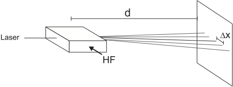
Fig. 15 The angles can be determined by measuring the distance between the first and the zero order maximum.
To do
Adjust the AOM so that the amplitude of the diffraction pattern is approximately symmetric in both \(\pm1\) orders. Measure the diffraction angles of the first and second order maxima for different frequencies, see Fig. 15. This AOM can work at \(110\pm25\) MHz, use a suitable stepsize. You can increase the precision of your result when you reduce the relative errors in your measurement; construct your set-up accordingly.
Measure the power in one first order maximum, relative to the power in the undiffracted beam, vs. the frequency of the sound wave in the same range and stepsize as before. Make sure beforehand that the photodiode is not saturated and reduce laser power if necessary (e.g. using a polarizer and PBS to couple power out of the main beam.)
Optimize the power in the first order maximum. Determine the relation between the power in the first order maximum, relative to the power in the un-diffracted beam vs. the amplitude of the sound wave, see also Fig. 13. Make sure beforehand that the photodiode is not saturated, as before.
Parameter |
value |
|---|---|
Optical wavelength |
\(\lambda=632.8\)~nm |
AOM material |
TeO\(_2\) |
Crystal length |
\(L=20\)~mm |
Indices of refraction |
\(n_o=2.261\) |
at \(\lambda=633\)~nm |
\(n_e=2.142\) |
Evaluation
Plot and evaluate the data of your measurements.
Determine the sound velocity in the AOM-crystal.
What is the wavelength of the sound in the crystal? On how many grating periods does the light diffract?
Determine the sound power in the crystal at the optimum deflection efficiency.
Which elements in the AOM-set-up determine the optimum working frequency?
Two perpendicular AOMs
For the next series of experiments, adjust two AOMs perpendicular to each other, so that the laser beam traverses both AOMs, see Fig. 16. Put both AOMs close (\(\stackrel{<}{_\sim} 1\)cm) to each other.

Fig. 16 A set-up with two AOMs perpendicular to each other
On the optical table, you will find a box with one input-port and two output-ports. This is the so-called phase-shifting box. The phase-shifting box takes a single input signal which it transmits to both output ports. When the incoming signal is periodic, the box allows you to delay the output on one output port, thus to change the relative phase between both output signals. The box also allows you to add a voltage offset to each output signal independently. For the operation of the phase-shifting box you have to create \(0V\) and \(\pm 18\)V. This only works with the power supply that has two independent outputs that allow to produce more than 18V individually.
To do
Connect each output of the phase-shifting box to the frequency-control inputs of one AOM driver. Do so via the oscilloscope, so that you can monitor that the applied voltages remain inside the allowed boundaries.
What diffraction pattern of the laser do you expect? What do you get?
What happens to the diffraction pattern when you change one or both of the offset voltages? Why is that?
Now connect the function generator to the phase shifting box input. It may be enlightening to switch the oscilloscope between YT-display (regular format) and the XY-mode. Here channel 1 is displayed as X, channel 2 as Y on the oscilloscope display. Note that the signal offset-value is not shown when the oscilloscope is in XY-mode.
Make sure you stay within the limits.
Next step:
What happens to the diffraction pattern when you modulate the sound amplitudes at a modulation frequency of \(\sim 1-100\)Hz? And above? And for different input wave forms?
What happens to the diffraction pattern when you modulate the sound frequencies of both AOMs simultaneously at a modulation frequency of \(\sim\)1-100Hz? And above? And for different input wave forms (sine, triangle, block)?
Observe and explain the diffraction patterns at a relative phase difference between both output channels of 0\(^\circ\), 90\(^\circ\), and 180\(^\circ\).
Compare the diffraction spots of the zeroth and first rows and columns respectively for each relative phase difference. How are the patterns connected to each other? Can you use the previous steps to draw a circle with the \((\pm 1,\pm 1)\) or \((\pm 1,\pm 2)\) order? And with the \((\pm 2,\pm 2)\) order?
How do these effects relate to the polarization state of light, in the sense of two perpendicular oscillating fields? Evaluate your observations in this part of the practicum in relation to what you learned in the first part of the practicum.
The phase-shifting box and its effect on the pattern of the \((\pm 1,\pm 1)\) order can be seen as the analogue to another part of the practicum: which part?
Connect each AOM to a different function generator (again via the oscilloscope). In this way, you can observe the effects of having different frequencies and varying relative phases between both modulation signals. The phase-shifting box is unnecessary here. (You might have to borrow the second frequency generator from your colleagues for a couple of minutes).
Try to modulate the sound frequency of one AOM exactly twice, three times,…, as fast as the other one. What happens when the modulation is not exactly \(n\) times the other? How can you tell when the phase difference is stable?
Can you now draw a circle with the \((\pm 1,\pm 2)\) order? And with the \((\pm 2,\pm 2)\) order?
How do these effects relate to the polarization state of light in the sense of two perpendicular oscillating fields?
What is the difference between a laser and ‘regular’ light (e.g.\ from a light bulb)?
What do the coherence time and -length of a laser mean?
Note
AOMs are used for several purposes. Usually the zeroth order, the un-diffracted beam, is blocked and only the first order is used. With an AOM one can realise a fast switch for optical signals, since the switching time is determined by the intensity slope of the sound pulse and its velocity inside the crystal. Switching times of \(\sim 10\)ns can be reached.
In atom-optical or spectroscopic experiments the frequency shift of the orders is used: the wavelength (frequency) of a laser is fixed to some convenient value near the frequency desired for the experiment. AOMs then allow to generate several different frequencies for the experiments all derived from the same center frequency delivered by the single laser, rather than to have to build several lasers.
Other purposes use the scanning function when sweeping the input frequency: e.g. laser shows. But the most prominent use is the use in laser-printers: AOMs deflect a laser beam across an electrically charged drum and induce a small, local discharge. At these spots toner particles will stick, which can then be stamped onto the paper. In this case two-dimensional deflection is performed by having two piezo-elements on different faces of a single crystal, rather than having two independent AOMs.
- 1
\(M_2 = n_0^6 p^2 / \rho v_s^3\), with \(n_0\) the refractive index, \(p\) the photo-elastic constant, \(\rho\) the material density and \(v_s\) the sound velocity in the crystal.
- 2
in principle one can change the VCO-input voltage - and thus the generated frequency - by turning the screw under Frequency. This should only be done by the tutor!
- 3
In principle one can change the default signal amplitude by turning the screw under
Amplitude. This should only be done by the tutor!